Basic Motor Control
The Raspbot_V2 comes equipped with 4 motors connected to Mecanum wheels with motor id 0, 1, 2, 3.
| Left | Right |
|---|---|
| 0 | 2 |
| 1 | 3 |
The motors can be controlled one at a time using the following methods:
 # motor id can be 0, 1, 2 or 3
motor_id = 1

# 0 is forwards, 1 is backwards
motor_dir = 0

# ranges from 0 to 255
motor_speed = 100

bot.Ctrl_Car(motor_id, motor_dir,motor_speed):
The Ctrl_car methods requires an additional argument for direction. To use negative values to represent backwards motion, use the Ctrl_Muto method.
# motor id can be 0, 1, 2 or 3
motor_id = 1

motor_speed = -20 # ranges from -255 to 255
# positive values -> move forwards
# negative values -> move backwards

bot.Ctrl_Muto(motor_id, motor_speed):
Stopping The Motors
The motors can be stopped by setting the motor_speed argument to 0.
Controlling Car's Directions (Simple)
Since the car is equipped with Mecanum wheels, not only can we move forwards and backwards, we can move in all the 8 directions without rotating the robot.

Forwards Movement \(\uparrow\)
| Left | Right |
|---|---|
| 0 \(\uparrow\) | 2 \(\uparrow\) |
| 1 \(\uparrow\) | 3 \(\uparrow\) |
Backwards Movement \(\downarrow\)
| Left | Right |
|---|---|
| 0 \(\downarrow\) | 2 \(\downarrow\) |
| 1 \(\downarrow\) | 3 \(\downarrow\) |
Leftward Movement \(\leftarrow\)
| Left | Right |
|---|---|
| 0 \(\downarrow\) | 2 \(\uparrow\) |
| 1 \(\uparrow\) | 3 \(\downarrow\) |
Rightward Movement \(\rightarrow\)
| Left | Right |
|---|---|
| 0 \(\uparrow\) | 2 \(\downarrow\) |
| 1 \(\downarrow\) | 3 \(\uparrow\) |
North-East (\(\nearrow\)) movement
| Left | Right |
|---|---|
| 0 \(\uparrow\) | 2 \(\text{off}\) |
| 1 \(\text{off}\) | 3 \(\uparrow\) |
South-West (\(\swarrow\)) movement
| Left | Right |
|---|---|
| 0 \(\downarrow\) | 2 \(\text{off}\) |
| 1 \(\text{off}\) | 3 \(\downarrow\) |
North-West (\(\nwarrow\)) movement
| Left | Right |
|---|---|
| 0 \(\text{off}\) | 2 \(\uparrow\) |
| 1 \(\uparrow\) | 3 \(\text{off}\) |
South-East (\(\searrow\)) movement
| Left | Right |
|---|---|
| 0 \(\text{off}\) | 2 \(\downarrow\) |
| 1 \(\downarrow\) | 3 \(\text{off}\) |
Rotate Counter Clockwise \(\circlearrowleft\)
| Left | Right |
|---|---|
| 0 \(\downarrow\) | 2 \(\uparrow\) |
| 1 \(\downarrow\) | 3 \(\uparrow\) |
Rotate Clockwise \(\circlearrowright\)
| Left | Right |
|---|---|
| 0 \(\uparrow\) | 2 \(\downarrow\) |
| 1 \(\uparrow\) | 3 \(\downarrow\) |
Moving At Any Angle
To generalize the movement of the mechanum wheels, we can use forces and vector decomposition to approximately control the angle the robot moves in.
Principle Of Mechanum Wheels
Regular wheels has a frictional force vector that's parallel to the direction of the wheel's travel which in turn results in a resultant force that's also parallel to that equal and opposite in direction causing the wheel to move forward (because the ground has a huge mass).

Mechanum wheels work on the principle the resultant force vector and the frictional forces can be decomposed into 2 forces \(45^\circ\) from that vector in the clockwise, and anti-clockwise direction.

However, due to the nature of mechanum wheels, they allow one of the vectors, either \(\vec{F_a}\) or \(\vec{F_b}\) to equals zero since the wheels can slip in one direction and gain traction in the other.
Here's a force diagram:
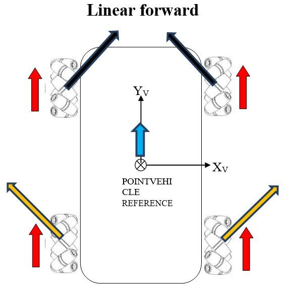
- Red arrows point in the direction in which the wheels rotate (top view)
- The other arrows, hence, are the forces "pulling" the car
For simplicity, we rotate the whole x and y axis by \(45^\circ\) counter clockwise. This will play an important part later.

Notice that there are pairs of vectors pointing in that of the new x-axis and y-axis. We combine their magnitude to construct the force vector acting on the car.
Where: - \(\theta\) is the angle from the new x-axis (after \(45^\circ\) rotation) - \(|\vec{F}| = \sqrt{F_x^2 + F_y^2}\) is the magnitude of the vector
Remember that \(F_x\) and \(F_y\) is made up by 2 force vectors from the wheels.
| Left | Right |
|---|---|
| 0 | 2 |
| 1 | 3 |
From the following labels:
And let the limit of the force that should be emitted by a motor to be \(F_\text{lim}\) and \(F_\text{lim}\)>0.
First, to simplify things, set each pairs of force vectors to be equals so that things get simpler.
Where: - \(F_{xm}\) is the force of motor \(0\) and \(3\) - \(F_{ym}\) is the force of motor \(1\) and \(2\)
Now we want to set either $|F_{xm}| = F_{lim} $ or \(|F_{ym}| = F_{lim}\) depending on whether which one has the bigger \(|\cos\theta|\) or \(|\sin\theta|\) value (absolute value is there since the motor will consume the same amount of power regardless of direction) so that one of the motor directions will maneuver at \(F_\text{lim}\).
Basically since:
We can simplify all this logic all to this: $$ \begin{cases} &F_{xm} = F_\text{lim}\times\frac{\cos\theta}{\max(|\cos\theta|,|\sin\theta|)}\ &F_{ym} = F_\text{lim}\times\frac{\sin\theta}{\max{(|\cos\theta|,|\sin\theta|)}} \end{cases} $$
However, since we can only control voltage via PWM signals, \(F_\text{lim}\) is a function of \(V\) where \(F_\text{lim}(V)\) is an increasing function for \(V\geq0\). Regardless, the angles stays the same and if we don't need to exactly predict what \(F\) is when \(V\) changes; there's no need to find \(F_{xm}\).
We still need to rotate the whole x and y axis back by \(45^\circ\).
But we can only control Voltage hence:
For simplicity (although it's not very accurate), we assume \(V \propto F\) so that given the same directions to control $ V_x$ and \(V_y\) will correspond to the direction of the force vectors \(F_{xm}\) and \(F_{ym}\) (because of Thales' theorem).
So:
To learn more or get better explaination see here and here.
Programmatically:
def move_robot(direction:float, power:float):
    """
    Moves the robot in a given direction

    Parameters:
    direction (float): the angle from the positive x-axis in the counter-clockwise direction in degrees
          90
          |
    180 -- -- 0
          |
         270

    power (float): a value from 0 to 1 representing the percentage of the max power of the motor

    Returns:
    tuple: speed set to 0, 3 motors and 1, 2 motors
    """
    # no parameter checking for simplicity
    angle_rad = (direction/360) * math.pi
    unit_vector = (math.cos(angle_rad - math.pi/4), math.sin(angle_rad - math.pi/4))
    max_component = max(unit_vector)
    speed = int(255*power)

    speed_x = speed*unit_vector[0]/max_component
    speed_y = speed*unit_vector[1]/max_component

    bot.Ctrl_Muto(0, speed_x)
    bot.Ctrl_Muto(3, speed_x)
    bot.Ctrl_Muto(1, speed_y)
    bot.Ctrl_Muto(2, speed_y)

    return speed_x, speed_y
Adding Ability To Rotate
To allow: - rotation - extreme left and right maneuvers - pivoting maneuvers
We must add an extra degree of freedom.
def move_robot(direction:float, power:float, turn:float, bot):
    """
    Moves the robot in a given direction

    Parameters:
    direction (float): the angle from the positive x-axis in the counter-clockwise direction in degrees
          90
          |
    180 -- -- 0
          |
         270

    power (float): a value from 0 to 1 representing the percentage of the max power of the motor

    turn (float): a value from -1 to 1 representing rotation to the left or to the right
    Returns:
    tuple: speed set to 0, 3 motors and 1, 2 motors
    """
    # no parameter checking for simplicity
    angle_rad = (direction/180) * math.pi
    unit_vector = (math.cos(angle_rad - math.pi/4), math.sin(angle_rad - math.pi/4))
    max_component = max(abs(unit_vector[0]), abs(unit_vector[1]))
    speed = int(255*power)

    speed_x = int((speed*unit_vector[0])/max_component)
    speed_y = int((speed*unit_vector[1])/max_component)

    clamp = lambda x: min(max(x,-speed), speed)
    # clamp function: f(x) = x if a < x < b; a if x < a; b if x > b

    bot.Ctrl_Muto(0, clamp(speed_x - turn*speed))
    bot.Ctrl_Muto(3, clamp(speed_x + turn*speed))
    bot.Ctrl_Muto(1, clamp(speed_y - turn*speed))
    bot.Ctrl_Muto(2, clamp(speed_y + turn*speed))

    return speed_x, speed_y